Latch On – Latch Off – 20 Series
What is a latching relay?
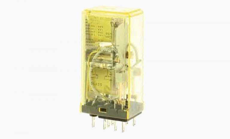
There are many different types of relays … electromechanical relays (EMR), solid-state relays (SSR), contactors, and the list goes on. A latching relay is a hybrid of electro-mechanical relays and the name ‘latching’ signifies a special internal construction to do just that – latch. While not a widespread common product, a latching relay is designed to latch on – keeping a device on without the need for power, then off once power is applied again. In addition to the term ‘latching’ you may also be familiar with ‘impulse’ or ‘bi-stable’ relays. All of these define the construction method above for either PCB or general-purpose construction.
Let’s explore further…
Benefits
Over traditional relays, latching relays open up design opportunities. In lighting circuits the use of a latching relay allows activation from a variety of input sources to a specific relay. This way panel switches and infrared sensors can activate a relay as required. Another benefit is power consumption. Latching relays do not require the coil to stay energized, only milliseconds, thus lowering system power demands.
Latching relay construction
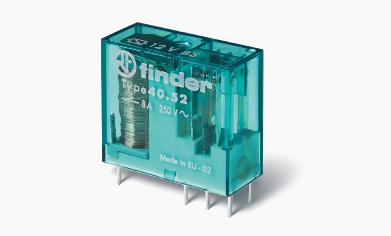
Single-coil – In this approach the relay is constructed in a more traditional method – contacts and coil. Here the approach is with polarity. Pass input power to the coil in one direction, say with the positive to the A1 terminal, and the contacts will change state. Reverse that same input power, now a negative polarity to A1, and the contacts will revert back or reset to their original state. The main challenge in utilizing a single coil construction is just that – one coil. When designers layout circuits it is not always easy to offer both: a standard and reverse polarity power flow. For applications using this construction, Finder offers our 40 Series single coil latching or ‘bi-stable’ relay.
Dual-coil – With this method the above approach of reversing polarity in a coil is replaced with two separate coils. Energize one and the contacts will ‘latch’, then by energizing the second coil the contacts reset. This allows for a wider variety of system design including activation from two separate power sources. Here the first coil activates from one source and resets via the second coil from the second power source.
Sequential latch or step relay – Somewhat in the same family, this version uses a similar process but offers an extra feature – steps. The internal construction consists of a coil and contacts with a mechanism that latches contacts on when coil is energized. This mechanism is designed in such a way that each pulse from the coil moves forward or ‘steps’ to the next set of contacts. If there is only one set of contacts, it would step on and off latching the contacts in place with each momentary coil pulse. Now add more contacts to the relay and the number of steps increases with contact groups stepping through the sequence and eventually back to their original position.
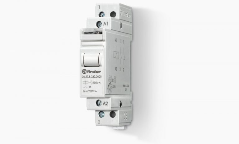
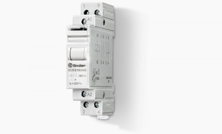
20 Series modular step relay
Here we are introducing our DIN-Rail mount product – the 20 Series. With a width of only 17.4 mm and no socket required, the 20 Series offers great flexibility and functionality in system designs. Contact ratings of 16 A as well as specific lamp load ratings provide a solution for a wide range of applications.
Specifications
– Single or double pole
– 16 A @250 V AC contact rating
– 30 A maximum peak current
– AC or DC coil options
– AgSnO2 contact material designed for lamp and high in rush loads
– short minimum impulse duration at 0.1 s
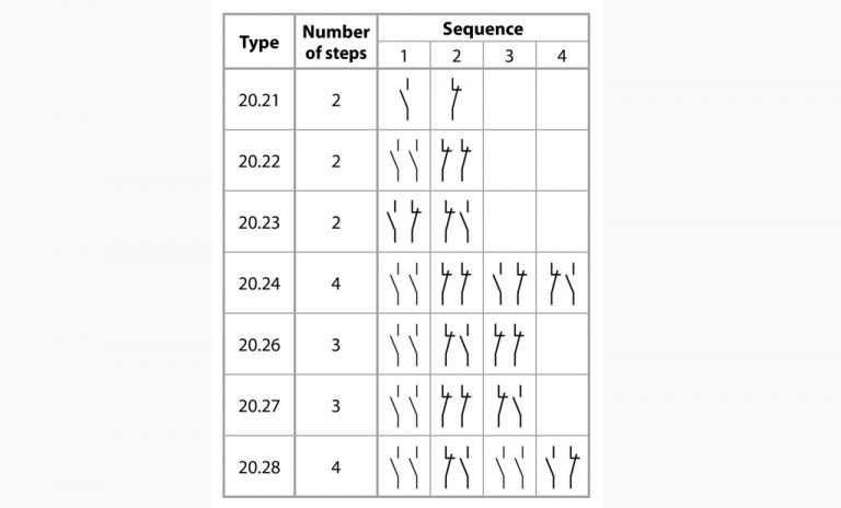
So how many steps?
The first type 20.21 offers a simple design with 1 NO and 1 NC contact – or a single step. Activate power to the coil and the relay changes state, closing the contact. Activate the coil again and this time the relay changes state opening the contact. On each impulse the relay will change state to the next contact group depending on the type. The series offers a variety of options with each changing the contact set up providing up to 4 steps, each varying the contact closures.
Application/specific uses

– Lighting (indoor and outdoor)
– Applications where it is critical to conserve power
– Conveyors, motors, pumps
– HVAC
– Contact retention in case of input failure
– Shades and shutters
The concept of step relays traces back many decades. In fact during 1954 Finder was founded by Piero Giordanino, the pioneer of the modern step relay. Even today, almost 70 years later, Finder’s step relays are providing present approaches to system design in a wide variety of applications.
Step up to the 20 Series.
Book a Finder-15 Video Sales Call to discuss your configuration and thermoregulation products in detail.

See the difference. Explore the difference. Enhance your designs with Finder.