Precautions for the safe use of a PCB relay
What is a PCB relay?
A PCB relay, which may also be referred to in full as a printed circuit board relay, or in short as simply a print relay, is designed to be soldered to a printed circuit board. The PCB itself electrically interconnects multiple electronic components by providing conductive tracks, pads and other features etched from one or more layers of copper, laminated on or between, layers of a non-conductive substrate.
PCB relays are most commonly of ‘through hole‘ style where the relay ‘pins‘ are inserted into holes in the PCB; although so-called surface mount PCB relays do exist. Finder’s range are all ‘through hole’ and range from small, low current relays, such as Finder’s 30 Series to PCB mount versions of industrial and power relays such as Finder’s 55 and 67 Series.
Finder’s 45 Series is a PCB relay with an integrated ‘250 Faston’ option. The integral Faston tab makes them particularly well suited to many domestic appliance applications. Some Finder PCB relays can also be mounted on a corresponding DIN rail socket for direct wiring. And for those relays, there is usually an equivalent PCB mounted socket that allows PCB inter-connection but with the convenience of relay replacement without a de-soldering operation.
How do you test a PCB relay?
As there will often be other electronic circuitry attached to the coil and the contacts, some care will be required during in situ testing.
If the surrounding circuitry is not understood, the test results may be misleading, or damage may occur if inappropriate voltages are applied. To test a PCB relay out of a circuit, the acceptable procedures are similar to an industrial relay.
Creating a simple test fixture using a socket, if one is available, will help prevent damage as large test connectors will not be hanging from the fine relay pins. Stresses applied to the relay pins may be transferred to the relay’s internal components.
PCB relays common precautions
Mounting
The PCB should have the hole sizes and spacings as stated in the Finder data sheet to avoid stress being applied to the pins on insertion.
Relay pins should NOT be bent in an attempt to secure the relay to the PCB. (The bending stresses will be transferred to the internal components and so affect reliability.) The use of plated through-hole PCBs give the strongest mechanical solder joint which is a significant factor with PCB mount industrial and power relays.
Cropping
Cropping of relay pins before or after soldering is not recommended. The cropping process may cause shock to the relay’s mechanism.
Flux Application
Finder PCB relays are usually available with 3 levels of environmental protection.
RTI – Dust Proof. Intended for Manual soldering only. Careful manual application of flux only.
RTII – Flux resistant. The relay is not fully sealed but is intended to be used with in an automatic soldering process. Automatic flux application is possible with care.
RTIII – Wash Tight. These relays will not normally be vulnerable to flux ingress from automatic application. The relay is sufficiently well sealed to be subjected to a short-term post soldering wash process for flux residue removal etc and is intended to be used within an automatic soldering process. This is NOT a sealed or hermetically sealed relay.
Preheating
Set the preheat time and heat to just achieve the effective evaporation of the flux, taking care not to exceed a component side temperature of 120 °C (248 °F).
Soldering
Set the height of the molten solder wave such that the PC board is not flooded with solder. Ensure the solder temperature and time are kept to 260 °C (500 °F) and 5 seconds maximum. Please note: Finder relays are not suitable for infra red or vapour phase reflow processes or similar.
Cleaning
Ultrasonic cleaning is not allowed, and aggressive solvents must be avoided.
After soldering and before starting any cleaning process, cooling of the PCB assembly must take place to reduce thermal stress and avoid pressure difference between the relay interior and its surroundings. Such conditions may cause the sealing to be breached.
In washing cycles, the solvent temperature must not be higher than 50 °C, and the difference of the temperature of cleaning and rinsing liquids must not exceed 10 °C.
Venting
After cleaning it is suggested to break open the venting pip on the relay cover. This is necessary to guarantee the electrical life at maximum load as quoted in the catalogue; otherwise, ozone generated inside the relay (dependent on the switching load and frequency) will significantly reduce the electrical life.
Finder’s range of PCB relays
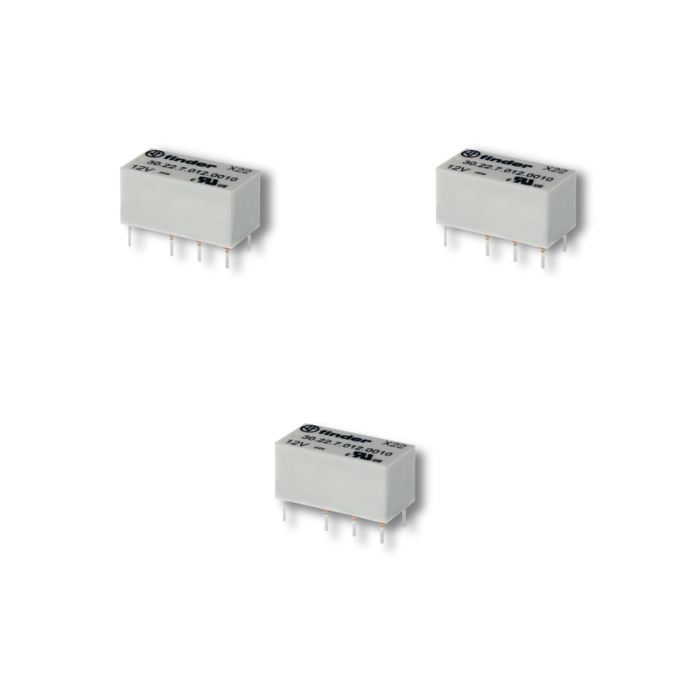
30 Series – Subminiature DIL relays 2A
The 30 Series consists of a 2 A dual inline relay for PCB mounting with the following features (according to Type):
- 2 Pole changeover contacts
- Low-level switching capability
- Subminiature: – industry-standard DIL package
- Sensitive DC coil: 200 mW
- Wash tight: RT III
Applications: Electronic circuit boards, Hi-Fi systems, Printers, Toys, Medical and dentistry, Hoists and cranes, Door and gate openers
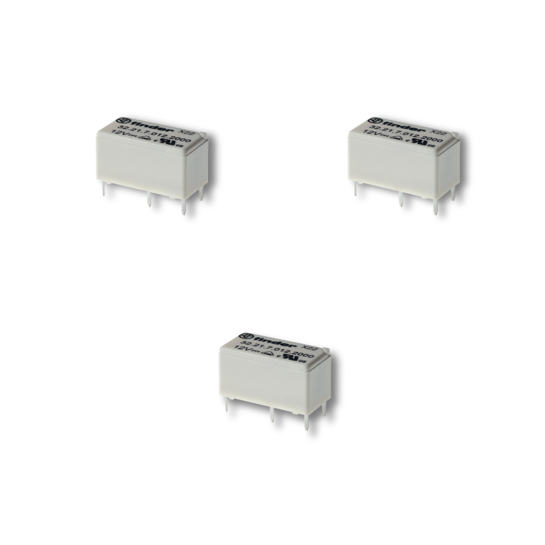
32 Series - Subminiature PCB relays
The 32 Series comprises miniature 6 A relays for printed circuit board mounting with the following features (according to Type):
- 1 Pole changeover contacts or 1 Pole normally open contact
- Subminiature, low profile package
- Sensitive DC coil: 200 mW – Wash tight: RT III
Applications: Copiers, Hi-Fi systems, Washing machines, Control systems, Electronic kits, Medical and dentistry, Electronic circuit boards, Programmable controllers.
34 Series - Slim P.C.B. Relays (EMR or SSR) 0.1-2-6A
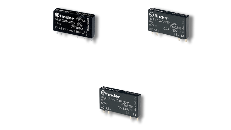
The 34 Series (EMR) relays include the following features (according to Type):
- Sensitive DC coil: 170 mW
- 5 mm wide – 6kV (1.2/50 μs) isolation, coil – contacts
The 34 Series (SSR) relays include the following features (according to Type):
- Sensitive DC input circuits
- 5 mm wide
- Silent, high speed switching with long electrical life
Applications: Bottling plant, Packaging machines, Labelling machines, Burners, boilers and furnaces, Timers and lighting controls, Electronic circuit boards, Programmable controllers.
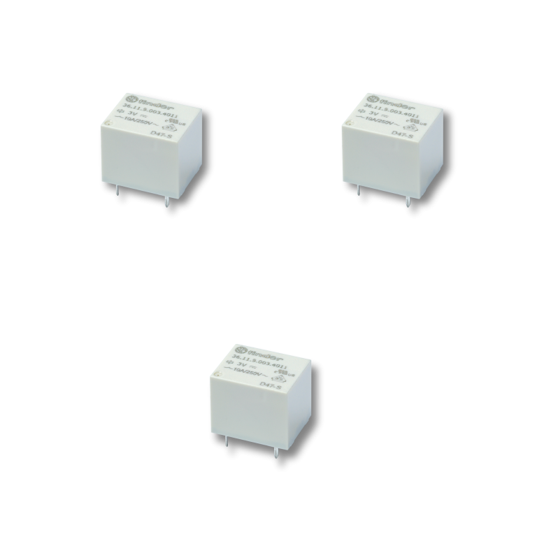
36 Series - Miniature PCB Relays 10A
The 36 Series comprises a miniature relay suitable for PCB mounting including the following features (according to Type):
- 1 Pole changeover contact
- Miniature “Sugar Cube” package
- DC coil: 360 mW
- Wash tight: RT III
40 Series - Miniature PCB Relays 8 - 10 - 12 - 16 A
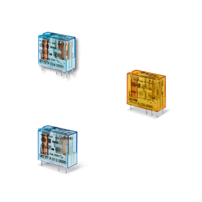
- DC coils, 500 or 650 mW
- 3.5 or 5.3 mm pin length
- 8 mm, 6 kV (1.2/50 μs) isolation, coil – contacts
- Flux proof: RT II standard (RT III version available)
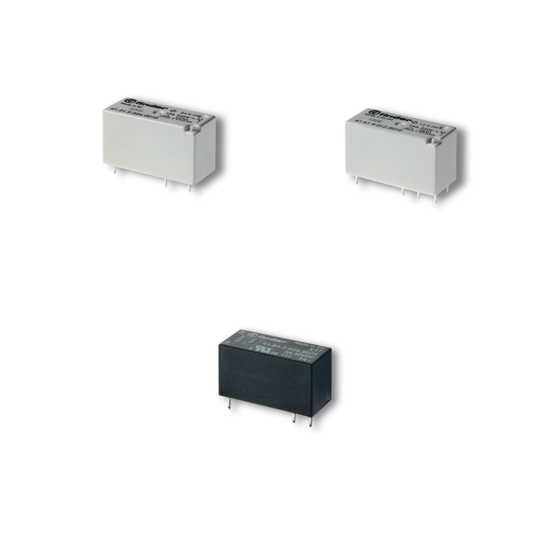
41 Series - Low-Profile P.C.B. Relays 3 - 5 - 8 - 12 - 16A
The 41 Series is a range of miniature low profile printed circuit board relays (height 15.7 mm). The different Types that make up this Series are:
EMR version
- Low profile, 15.7 mm height
- AC & DC coils
- 8 mm, 6 kV (1.2/50 μs) isolation, coil – contacts
- Flux proof: RT II standard, (RT III option)
Solid State (SSR) version
- Low profile, 15.7 mm height
- Sensitive DC input circuits
- Silent, high speed switching with long electrical life
43 Series - Low-Profile P.C.B. Relays 10 - 16A
The 43 Series is a range of miniature PCB relays with the following features (according to Type):
- Low profile, 15.4 mm height
- Sensitive DC coils: 250 mW or 400 mW
- Very high coil contact isolation 10 mm, 6 kV (1.2/50 μs)
- Flux proof: RT II standard, (RT III option)
- 3.2 or 5 mm pin pitch
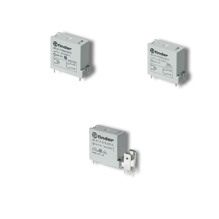
45 Series - Miniature PCB Relays 10 - 16A
The 45 Series products are miniature PCB relays for high ambient temperature + 105 °C / + 125 °C with the following features (according to Type):
- Sensitive DC coil: 360mW
- Relay for +125°C ambient use
- Contact gap ≥ 3mm according to EN 60730-1
- 8mm, 6kV (1.2/50 μs) isolation, coil – contacts
- PCB mounting + 250 Faston